


0 INTRODUCTION
With development of the economy, environmental pollution and energy crisis have become important issues that hinder social development. Countries have begun to turn their attention to the development of new clean energy. Microgrid technology can realize the efficient use of renewable energy and conventional energy. It is the materialization of the smart grid at the user end and an important carrier for promoting the development of energy and mana-gement methods[1]. However, the randomness and intermittent nature of distributed power generation output will have a great impact on the safety and stability of the microgrid. In order to ensure the safe and stable operation of the system, the energy storage device becomes an important part of the microgrid system[2].
According to the energy density and power density of the energy storage method, we can divide it into two energy storage types: energy storage and power storage. Energy storage includes chemical energy storage, compressed air energy storage and pumped energy storage. It has the characteristics of large charge and discharge capacity and high energy density. The disadvantage is that the power density is low. The main application occasions are peak-shaving and valley-filling, backup power supply and adjust the load, etc. Power storage includes supercapacitor energy storage, superconducting energy storage and flywheel energy storage. It has the characteristics of high power density, long cycle life and short charging and discharging time. The disadvantage is that the storage energy is small, and the main application occasion is to improve power quality and regulation of the transient stability of the grid[3]. When the microgrid is running in the grid, the peak-to-valley difference of the load and the volatility of the distributed generation usually coexist. Hybrid energy storage is more conducive to the safe and stable operation of the microgrid system than a single energy storage device.
Adding an energy storage device to the microgrid, the most important is the capacity allocation problem of the energy storage device. As the capacity of the energy storage system in the microgrid increases, the system reliability and power quality are higher, but the economy is reduced due to the increase in cost[4]. Therefore, it is necessary to find a better balance between system reliability and economy in combination with microgrid operation requirements. In addition, on the basis of meeting the economic operation of the microgrid, the constraints of the battery energy storage system should also be considered to extend its service life[5,6].
In this paper, the microgrid with renewable energy generation is taken as the research object. Based on the high energy and high power difference of the energy storage device, the energy storage device is divided into two types: power type and energy type. Considering the output requirements of microgrid for renewable energy generation, a weighted moving average control method is proposed to smooth the output power of distributed generation. At the same time, the upper and lower limit constraint control method is proposed to perform peak clipping and filling of microgrid system load.
1 THE ROLE OF ENERGY STORAGE DEVICES IN DISTRIBUTED GENERATION SYSTEMS
1.1 Smooth output fluctuation
In this paper, the output power smoothness of distributed generation is evaluated by the magnitude of active power fluctuation. The active power fluctuation refers to the absolute value of the power peak-to-valley difference of the total output curve within a specified time, and the active power fluctuation rate refers to the ratio of the active power fluctuation to the rated output power. Calculated as follows.
Active power fluctuations:
Active power fluctuation rate:
Where PV(t) is the average output power of the distributed power supply in the t period; Δt is the period of the set power variation, usually 5 min or 10 min;
The larger the β2, the greater the fluctuation of output, in this paper, the wind farm's 10 minute (Δt=10 min) rate of change does not exceed 10% as a limitation of the microgrid's output power volatility. That is, β2≤10% is required.
1.2 Load peak-shaving and filling valley
In this paper, we use the peak-to-valley difference rate to evaluate the peak-shaving and valley-filling effect. The evaluation indicators are calculated as follows.
Peak and valley difference:
Peak and valley difference change rate:
Where Pmax and Pmin are the maximum and minimum values of the combined load in one day; Pav is the average value of the combined load[8].
The larger β3 indicates that the load peak-to-valley difference is larger. If β3=0, it indicates that the integrated load of the microgrid can be stabilized into a straight line under the action of energy storage, that is, the integrated load is kept constant.
2 SMOOTH OUTPUT FLUCTUATION OPTI-MIZATION METHOD
2.1 Weighted moving average model
Through the charge and discharge control, the energy storage device quickly absorbs the “remaining power” or supplements the “power shortage” to achieve greater power regulation and reduce the impact that the microgrid may have on the main network. Smooth power fluctuations require energy storage systems with short-term power dynamics. Power storage systems such as super-capacitor energy storage, superconducting energy storage, and flywheel energy storage can be selected. In this paper, we use the super capacitor energy storage.
Considering the requirements of control accuracy and speed, this paper adopts an improved weighted moving average control algorithm. The control model is as follows[9].
Suppose the sampled data is x(1), x(2), x(3),...,x(K), and the sampling period is Ts. N is the sampling point of the current stage, that is, the control step size. Then, the continuous N sample point data is x(k-1), x(k-2), x(k-3),...,x(k-N), Then, the moving average of the N sampled data is:
After transforming equation (5) by z, the z-domain transfer function of the moving average model (MA) is obtained as
It can be seen from the above equation that the moving average model has a time lag of
Where ymwma is the output power value of the MWMA model; yma(k) is the output power value of the MA model; Tp is the lag time of MA equivalent to MWMA; τ is the response time of the energy storage device; ydif(k) is the trend value and its calculation process is as follows.
(1) The control step N is divided into M parts equally, and the moving average of each interval can be calculated by equation (8).
(2) Calculate the difference between the moving averages of the adjacent intervals, and find the trend value of each interval.
(3) Multiply the trend value of each interval by the corresponding weight w, then perform the summation operation, and finally divide by the interval time
Where w is the weighting factor, the closer to KTs, the greater the weight of the trend value, then w(i) can be expressed by equation (11).
Finally, the moving average yma(k) and ydif(k) obtained by the MA model are substituted into equation (7). The distributed power supply output power curve can be obtained.
2.2 Determination of control step size
The smoothness of the output power curve is affected by the control step size N. The larger the N, the smoother the output curve after control, and the larger the capacity of the required energy storage device. Conversely, the smaller the output curve, the larger the fluctuation of the output curve, and the required energy storage capacity is relatively reduced. In order to satisfy both the smoothness of the curve and the minimum capacity of the energy storage device, N is controlled. If the value of N gradually increases, when N=N*,β2≤10%, then N* is the optimal control step.
3 PEAK-SHAVING AND VALLEY-FILLING OPTIMIZATION METHOD
In this paper, the upper and lower limit constraint control method is used to control the peak clipping and filling. The upper and lower limit constraint control sets the upper and lower limits of the load demand curve, and calculates the charge and discharge power of the energy storage system according to the power difference between the load demand curve and the upper and lower limits.
After the energy storage device is added to the system, when the integrated load power is lower than the lower limit of the valley power, the energy storage device is controlled to be properly charged; When the integrated load power is higher than the peak power upper limit, the energy storage device is controlled to be properly discharged. Then the comprehensive load after the peak-shaving and valley-filling control is within the upper and lower limits, that is, it is considered that the peak-shaving and valley-filling effect is achieved.
To perform peak clipping and valley control on the load, first determine the size of Pup and Plow. The size of Pup and Plow is determined by equation (12).
Assume that the charging and discharging power of each period is:
Where Pb(t) is the charge-discharge power of the energy storage system; Pg(t) and P′g(t) are the actual values of the comprehensive load and the expected value after the peak-shaving and valley-filling.
The peak-shaving and valley-filling control strategy is as follows: the distributed power output and the load are superimposed to obtain the integrated load power Pg and compared with the power upper and lower limits. When Pg≥Pup, the load demand is too high, and the energy storage system discharge supplemental power difference is required at this time; When Pg≤Plow the integrated load is at a low point, the energy storage device needs to be put into operation, and is in a state of charge to increase the comprehensive load demand; otherwise, the energy storage device is out of operation.
4 CAPACITY CALCULATION OF ENERGY STORAGE DEVICE
The specific calculation steps for the maximum capacity required for the energy storage system are as follows.
(1) Calculate the ideal value of charge and discharge power of energy storage devices in each period
Where Pb(k) is the ideal value of the charging (discharging) electric power of the k-th control period energy storage system, and when it is greater than 0, it means that the energy storage system discharges; Pg(k) is the actual combined load of the k-th control period; Pref(k) is the expected integrated load power value, which is taken as the ideal load power after the peak-shaping control or the smoothing power fluctuation control.
(2) Accumulate the charge and discharge power of the energy storage system in the control period according to the determined actual output power of the energy storage system. At the end of the k-th control period, the remaining energy of the energy storage system is represented by E(k), then
Where Tc is the smoothing control period; E0 is the initial energy of the energy storage system.
(3) Calculate the maximum and minimum energy difference of the energy storage system during each control cycle. In order to meet the energy requirements of the smoothing process, the capacity W of the energy storage system to be configured is determined by the following equation.
Where max(E(k)), min(E(k)) represent the maximum and minimum capacity of the energy storage system during the entire sample data control cycle.
(4) Considering the limitation of the discharge depth, temperature and actual operating efficiency of the energy storage system, the capacity of the energy storage system can be corrected by the formula (17).
Where W is the capacity of the energy storage system under ideal conditions; A is the safety factor (generally the value is 1.1~1.4); K is the temperature correction coefficient (generally 1 is above 0 ℃,1.1 is taken above -10 ℃,and 1.2 is taken below -10 ℃); η is the power conversion efficiency of the energy storage system (taken 0.78); dDOD is the depth of discharge (generally 80%).
The capacity of the corrected energy storage device can be obtained according to equation (17).
In order to adapt to the randomness and intermittent nature of distributed power generation systems such as wind power generation and photovoltaic power generation, the energy storage system is required to have both high power density and high energy density. However, the battery has high energy density and short cycle life; while the supercapacitor has the opposite energy storage, its power density is high, but the energy density is low and the cycle life is long. Therefore, a typical hybrid energy storage system configuration scheme is to combine the two.
Assuming a distributed power supply rated at 100 kW, The average control step is divided into M=2 copies. When β2≤10%, the optimal control step is calculated as N*=25. The expected power after the smoothing by the weighted moving average control method, if the energy storage device is completely in an ideal state of charge and discharge, The capacity of the optional supercapacitor energy storage device is 21 kW·h. If factors such as depth of discharge and loss are taken into account, take a safety factor of 1.3, a temperature correction factor of 1.2, a conversion efficiency of 0.78, and a charge and discharge coefficient of 0.8, Then, according to equation (17), the energy storage capacity is corrected, and the calculated capacity of the energy storage device can be selected to be 52 kW·h.
Since the distributed generation output curve and the daily load curve are continuously changing,so discretizing data is good for optimizing calculations, discrete data is taken as the average of the actual data in the interval. This simulation analysis assumes that the maximum load demand in the system is 180 kW, distributed generation output active peak value is 70 kW. Then the distributed power output curve and load comprehensive demand curve are shown in Fig.1. The average demand is 128 kW. Assume that the grid requires the microgrid to meet the peak-to-peak fill index of ε3=20%. The peak-shaving effect after adding the energy storage device is shown in Fig.2.
图1
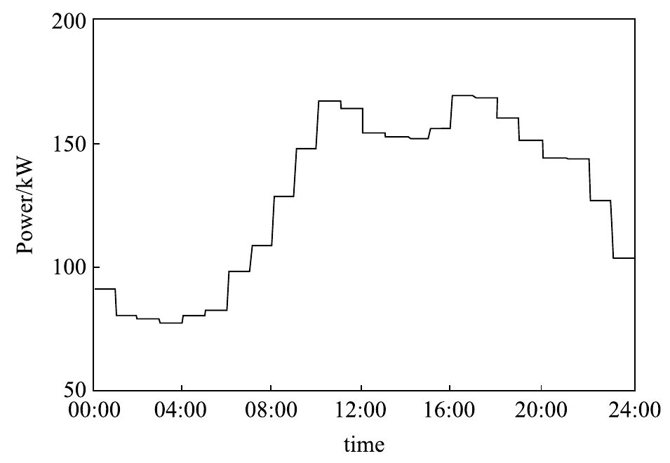
图1
微电网分布式发电与负荷综合曲线
Fig.1
Total power curve of distributed generation and load demands in microgrid
图2
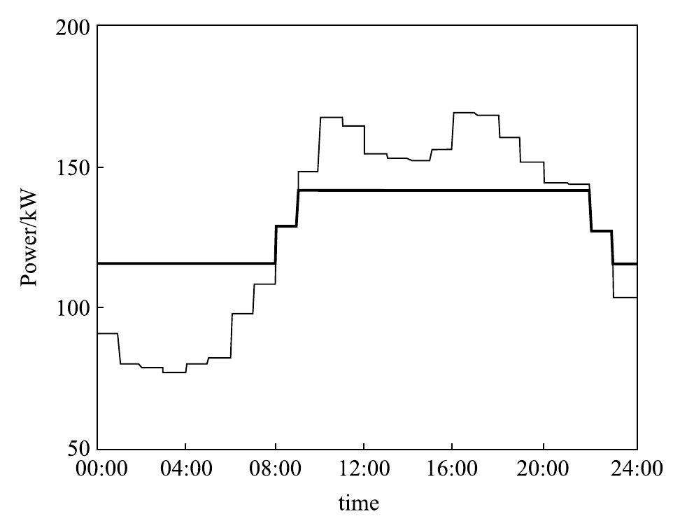
图2
储能系统削峰填谷控制效果图
Fig.2
Result of peak load shifting control by energy storage system
It can be seen from Fig.2 that the energy storage device is in a charging state during the period of 00:00-08:00 and 22:00-24:00, increase the system load to achieve the role of filling the valley; It is in a discharge state during the period of 10:00-22:00 to peak the clipping effect; It is neither charged nor discharged at 08:00-10:00 and 22:00-24:00. According to formula (17), take a safety factor of 1.3, a temperature correction factor of 1.2, a conversion efficiency of 0.78, and a charge and discharge coefficient of 0.8. The corrected capacity of the capacity battery storage device can be selected to be 570 kW·h.
5 SUMMARY
In this paper, a hybrid energy storage mode is proposed for the energy storage system in the distributed generation system, and the capacity configuration of the power storage device is calculated by the weighted moving average method to stabilize the power fluctuation of the distributed power supply of the microgrid. The upper and lower limit constraint method is used to calculate the capacity configuration of the energy storage device, and the microgrid integrated load is shaved peak and filled valley. Through these two control methods, the optimal energy storage device capacity configuration can be obtained, and the distributed power supply power fluctuation suppression and integrated load is shaved peak and filled valley in the micro-grid. Through the research on the optimal configuration of energy storage devices in distributed power generation systems, it is hoped that today, with distributed power generation more and more attention, it can provide reference for more stable power generation methods.
参考文献
Mean cost-based droop scheme in the application of distributed generators
[J].
平均成本下垂控制策略在分布式发电中的应用
[J].
Day-ahead scheduling optimization for microgrid with battery life model
[J].
计及蓄电池储能寿命影响的微电网日前调度优化
[J].
Capacity allocation of energy storage system considering its action moment and output depth in rapid frequency regulation
[J].
考虑储能参与快速调频动作时机与深度的容量配置方法
[J].
A capacity optimization method of hybrid energy storage system for optimizing tie-line power in microgrids
[J].
用于优化微网联络线功率的混合储能容量优化方法
[J].
Optimization calculation of wind farm storage capacity based on minute-scale wind power characteristic
[J].
基于风电功率min级分量波动特性的风电场储能容量优化计算
[J].
Optimal capacity allocation of energy storage in micro-grid with distributed generation
[J].
含分布式发电的微电网中储能装置容量优化配置
[J].
Capacity configuration of the hybrid energy storage system for wind power smoothing
[J].
平抑风电波动的混合储能系统的容量配置
[J].
Energy management for distribution networks with storage system——a hierarchic approach
[C]//


